
RF absorber fundamentals
An RF absorber reduces unwanted electromagnetic energy through electrical or magnetic losses inside the material. For reflection control, its surface and structure also help energy enter with less reflection. Together, these effects reduce the energy returning to a chamber, antenna, or electronic circuit.
Follow the absorption process
Low reflection requires matching and loss. Energy must enter the absorber and dissipate within it.
Performance belongs to a specific configuration. Frequency, material, thickness, shape, and backing work together.
Absorption complements shielding. A metal enclosure can block external signals while supporting unwanted resonances inside.
−20 dB reflectivity means 1% reflected power. Calling the remaining 99% “absorbed” also requires negligible transmission and a measurement that accounts for the relevant reflected energy.
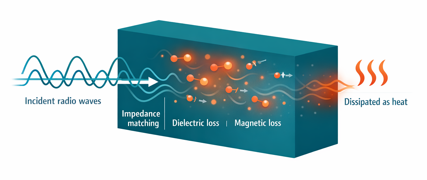
A sudden change in electromagnetic impedance sends part of an incident wave back. A suitable surface profile or arrangement of layers reduces this mismatch, allowing more energy into the absorber.
The alternating electric and magnetic fields interact with the material. Loss mechanisms convert some of that field energy into heat, reducing the wave’s amplitude as it travels.
The complete structure determines the remaining reflection. In a metal-backed design, energy reaching the backing returns through the lossy material, while phase relationships also affect the wave emerging from the front.
For a passive absorber in steady operation, incident power is divided into reflected, absorbed, and transmitted power, with all relevant outgoing directions included. Low reflection alone does not prove high absorption: a material that transmits most of the wave can also reflect very little.
Sources: PPG, Microwave Absorber Theory; Laird, Microwave Absorbing Foams
The absorbing filler determines much of a material’s electromagnetic behavior. Carbon-loaded foam and magnetic-particle-filled elastomers can both absorb RF energy, but their dominant loss mechanisms differ.
| Loss mechanism | What happens inside the material | Material examples |
|---|---|---|
| Dielectric polarization loss | Polarization does not follow the alternating electric field perfectly. The lag dissipates energy. | Lossy dielectric composites |
| Conductive or resistive loss | The electric field drives currents through finite resistance, producing heat. | Carbon-loaded foam and resistive films |
| Magnetic loss | The material’s magnetization responds with loss to the alternating magnetic field. | Ferrites and magnetic-particle-filled composites |
These categories can overlap in material data. Conductivity may be included in the effective dielectric loss, so “dielectric loss” and “resistive loss” are not always reported as separate contributions.
Complex permittivity describes the material’s electric response; complex permeability describes its magnetic response. Their real parts relate to energy storage and their imaginary parts describe loss, using the stated time convention. Engineers use their frequency-dependent values, together with geometry and boundary conditions, to model absorption. A high loss value alone does not guarantee low surface reflection.
Sources: Laird, Theory and Application of RF/Microwave Absorbers; Hexcel, Dielectric Absorber Foam
A wave approaching a pyramidal absorber encounters a small amount of material near the tips and progressively more toward the base. This graded transition helps reduce front-surface reflection. The material’s losses then dissipate energy; changing the wave’s direction alone is not absorption.
Additional depth often helps a broadband foam design operate at lower frequencies. Carbon loading and the arrangement of layers also affect matching and attenuation. Two panels with the same thickness can therefore have different performance curves.
A Salisbury screen uses a resistive sheet spaced approximately a quarter wavelength in the spacer medium from a conductive backing. This produces a matched, lossy structure around its design frequency. Other thin absorbers use patterned resistive surfaces and engineered substrates. Their useful bandwidth depends on the complete design.
No. Quarter-wave spacing describes particular resonant designs. Graded absorbers, magnetic composites, and engineered surface structures follow different design constraints. Even in a quarter-wave structure, the relevant wavelength is inside the spacer medium, not automatically the free-space wavelength.
Chamber hybrids often combine ferrite tiles with a matched tapered absorber to extend the usable frequency range. The tile, upper absorber, and backing form one electromagnetic system. Stacking unrelated materials does not establish the same performance.
Sources: PPG, Microwave Absorber Theory; Hexcel, Foam and Salisbury Screen Designs; Costa et al., Analysis and Design of Ultra Thin Electromagnetic Absorbers; TDK, EMC Solutions Overview
Repeated reflections inside a metal enclosure can reinforce fields at resonant frequencies. Adding absorber introduces loss and lowers the resonance’s quality factor, or Q, reducing the buildup of stored energy. Placement matters because the material must interact with the relevant field.
Absorber can also shift a resonance by changing the enclosure’s effective material properties. Check the surrounding frequency range after installation, not just the original problem frequency.
Close to a circuit trace or component, the electric and magnetic fields do not necessarily have the same relationship as a traveling plane wave. A thin suppression sheet should therefore be evaluated for the local coupling problem. A free-space reflectivity curve does not, by itself, predict circuit-level noise reduction.
Sources: MAST Technologies, The Use of Absorbers in Electronics; Laird, Free-Space, Cavity Resonance, and Near-Field Absorbers
When reflectivity is defined as 10 log10 of reflected power divided by incident power, −20 dB corresponds to 1% reflected power. More negative values indicate less reflection under the same measurement conditions.
| Reflectivity | Reflected power | Absorbed power if transmission is negligible* |
|---|---|---|
| −10 dB | 10% | 90% |
| −20 dB | 1% | 99% |
| −30 dB | 0.1% | 99.9% |
*The absorption column also assumes that the reflected-power value accounts for all relevant reflected energy. A low return measured in one direction can result partly from scattering elsewhere. A conductive backing can make transmission negligible, but the measurement geometry still matters.
Return loss uses the opposite sign: a −20 dB reflection-coefficient magnitude corresponds to a positive 20 dB return loss. Check the definition when a datasheet uses “reflection loss,” “attenuation,” or “absorption” as its label.
For a calibrated, power-normalized two-port measurement that captures the relevant reflected and transmitted modes, R = |S11|², T = |S21|², and A = 1 − R − T. Use linear magnitudes before squaring, not dB values. If additional scattering, polarization conversion, or fixture losses are unaccounted for, missing measured power cannot automatically be assigned to material absorption.
Match frequency, incidence angle, polarization, backing, sample dimensions, and test method. Distinguish typical results from guaranteed limits. Insertion loss measures a change in transmission through a setup; it can include reflection and other effects as well as absorption.
Sources: Keysight, Reflection Measurements; Scientific Reports, An Equivalent Realization of Coherent Perfect Absorption under Single Beam Illumination
Identify the unwanted energy path first, then choose a material and a measurement that address it.
| Problem | Absorber starting point | Result to verify |
|---|---|---|
| Reflections in a chamber or antenna test area | Pyramidal, graded foam, or a chamber-specific hybrid | Reflection control and measurement quality across the required test volume |
| Resonance inside a metal enclosure | Lossy foam or magnetic sheet placed to interact with the resonant field | Resonance reduction across the affected band after the enclosure is reassembled |
| Local coupling near a PCB or component | A near-field suppression sheet selected for the local field and spacing | Noise reduction together with the intended circuit or antenna performance |
For enclosure lining and localized treatment, compare sheet materials by their intended application and supporting data.
When clearance is the main constraint, establish the maximum installed thickness before reviewing ultra-thin options.
Include the adhesive, backing, air gaps, seams, and mounting orientation in the evaluation. Preserve ventilation and component clearances. Because absorbed RF power becomes heat, confirm continuous and pulsed power limits for the actual airflow and ambient temperature.
Record a baseline, change the absorber configuration, and repeat the same test with cables, antennas, fixtures, and operating settings held constant. Check both the unwanted response and the useful signal. Keep the configuration only if it improves the result that matters to the application.
Sources: Laird, Absorber Applications; MAST Technologies, Electronic Applications; ETS-Lindgren, High-Power Absorber Design
Acoustic foam is designed for sound. RF absorber foam uses an electromagnetic loss system, such as conductive carbon loading. Similar shape or color does not establish RF performance; use material with RF data for the intended application.
Not necessarily. At low absorbed power, the temperature rise may be too small to notice. High-power exposure can produce substantial heating, so surface temperature is neither a reliable measure of absorption effectiveness nor a substitute for the manufacturer’s power limits.
Every practical absorber has a useful operating range. Broadband products cover a specified band, and their performance still varies within it. Request the curve for the exact grade and installed thickness.
Yes. Absorber interacts with the fields reaching it, including useful antenna fields. Placement can affect efficiency, matching, and the radiation pattern. Verify antenna performance as well as interference reduction.
Next step
Use the operating band, available space, and unwanted energy path to narrow the options. Then request data or samples that match the proposed installation.
Compare RF absorber typesAdvertiser Disclosure:
We receive compensation from some of the companies listed below.This compensation may affect which companies are included and the order in which they appear.
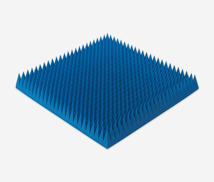
| Frequency Range |
|---|
| 3GHz-320GHz |
| Material |
| Urethane Foam |
| Key Features |
| Up to 50 dB of absorption |
At just 550g per panel—approximately half the weight of competing products (*1)—this polyurethane foam absorber covers a wide frequency range from 3 to 320 GHz.
Delivers 50 dB absorption, outperforming conventional heavy ferrites.
Velcro-backed for rapid mounting, ideal for temporary setups and cost-effective maintenance.
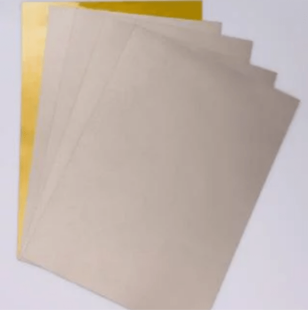
| Frequency Range |
|---|
| 20MHz-3GHz |
| Material |
| Elastomer |
| Key Features |
| Permeability (at 1 MHz): 150 |
Heat-resistant elastomer: Designed for direct SMT processing and high-temperature durability.
Ultra-thin (from 0.1 mm) for high-density integration with robust EMI suppression.
It significantly reduces assembly workload and enables EMI countermeasures without altering the existing manufacturing process.
| Frequency Range |
|---|
| 1-35 GHz |
| Material |
| Elastomer |
| Key Features |
| Reflection Performance: –20 dB |
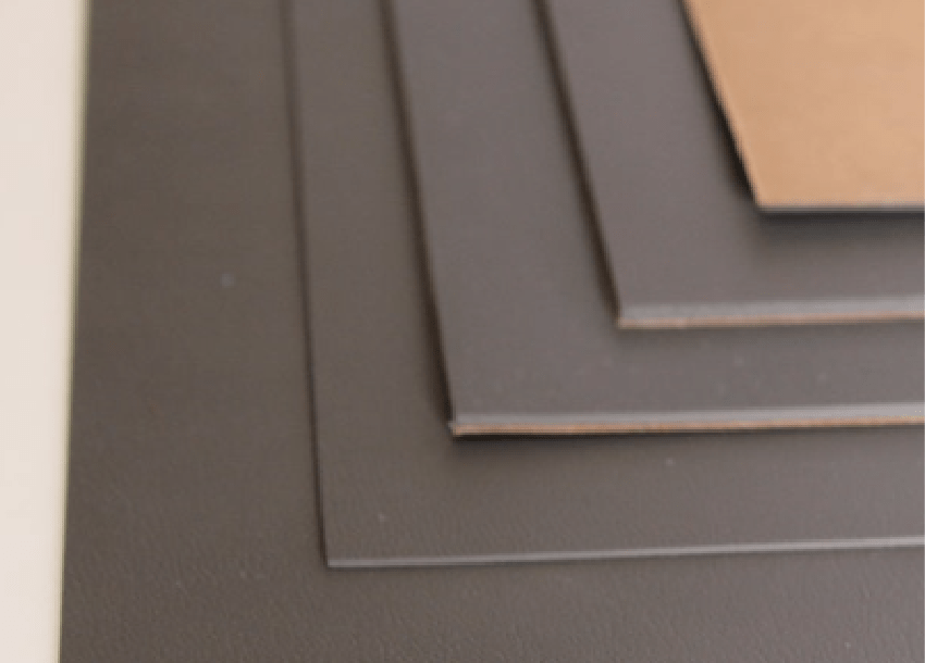
Frequency-tuned for specific radar absorption, offering superior stealth performance over standard RF sheets (*2).
Millimeter-thin design delivers –20 dB reflection, ensuring high absorption while preserving aerodynamic integrity.
Excellent conformance to complex geometries with thermal stability from –60°C to 150°C—ideal for aerospace platforms.