
Hybrid RF Absorber Selection Guide
Hybrid EMC absorbers combine ferrite tiles with specially designed pyramidal absorbers to reduce reflections across a wide frequency range. They are commonly used in EMC test chambers, where absorber performance affects the design and usable space of the facility.
When comparing products, consider performance across the required frequency band, total installed depth, test geometry, and RF power exposure. The chamber layout and installation method also need to be taken into account.
See what to check when selecting a hybrid absorber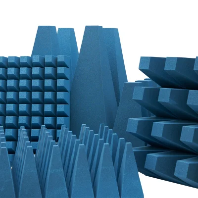
Header image: WAVASORB® VHY product example. Source: E&C Anechoic Chambers
A hybrid RF absorber typically consists of ferrite tiles covered by a pyramidal absorber designed to work with them. This combination is used in EMC chambers to reduce reflections over a wider frequency range than either component is designed to handle on its own.
The ferrite tiles and pyramidal absorber must be designed to work together. Adding a general-purpose foam absorber over existing ferrite tiles does not guarantee the performance of a purpose-built hybrid system.
Sources: MVG, UH Series technical data ; ETS-Lindgren, DSH-400H
Hybrid absorbers are widely used in chambers for radiated emissions and immunity testing. The required absorber coverage, including any floor treatment, depends on the measurement procedure and chamber configuration.
Hybrid absorber systems are also available for automotive and military EMC testing facilities. Requirements vary by test method, particularly the frequency range and field strength involved. Check the specifications for the intended test rather than relying on general application categories.
Hybrid absorbers can be used in compact chamber designs. When planning the layout, account for the full installed depth of the absorber system, including the ferrite tiles and mounting hardware. This affects the space available for equipment, antenna movement, and access within the chamber.
Sources: E&C, WAVASORB® VHY applications ; ETS-Lindgren, FACT 3 Chambers
Start with the chamber's testing requirements, then compare absorber performance and installation needs. The following checks can help narrow down suitable configurations.
Identify the relevant emissions or immunity tests, frequency bands, test distance, equipment dimensions, and measurement area. These requirements determine what the absorber system must support.
Use the reflectivity data for the specific absorber model. A peak absorption figure does not describe performance across the entire frequency band. Compare the published curves or tables at frequencies relevant to your testing.
Review the specified ferrite tiles, mounting substrate, attachment method, seams, and total installed depth. For chamber upgrades, ask the supplier whether the existing ferrite can be reused.
Check the absorber's power-handling limits against the expected RF exposure. Also request documentation covering temperature, humidity, fire testing, and cleanliness requirements for the selected configuration.
Agree with the supplier on how the completed chamber will be tested and accepted. Material reflectivity and chamber-level measurement performance are separate considerations. Both need to be addressed during the project.
References: E&C, VHY installation and validation ; ETS-Lindgren, FACT 3 chamber specifications
The following products use different materials and configurations. Compare their frequency specifications and dimensions alongside the performance data for each model.
| Product | Hybrid construction | Published frequency range | Dimensions |
|---|---|---|---|
| WAVASORB® VHY | Ferrite tiles with truncated pyramidal absorbers | 9 kHz–100 GHz; performance varies by model and frequency | 60 × 60 cm footprint; height varies by model |
| HyPyr-Loss™ Ultra UH Series | Polypropylene pyramidal absorbers designed for ferrite tiles | 30 MHz–40 GHz | 60 × 60 cm base; listed heights of 30, 50, or 75 cm |
| DuraSorb™ DSH-400H | Polystyrene absorber with a ferrite substrate | 30 MHz–40 GHz in the electrical specifications | 60 × 60 cm footprint; 45.6 cm high including ferrite base |
Check whether the listed height includes the ferrite tiles and mounting hardware. This is particularly important when comparing products for chambers with limited space.
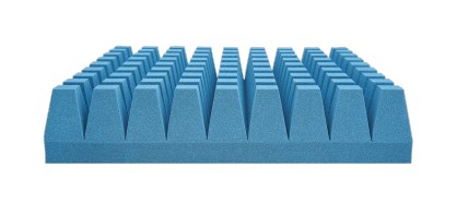
WAVASORB® VHY combines ferrite tiles with truncated pyramidal absorber elements. The system can be installed permanently or mounted in modules that allow individual sections to be replaced or maintained.
Reflectivity varies by model and frequency. The manufacturer provides normal-incidence reflectivity data for individual models. Use these figures when comparing configurations rather than applying the series' best published value to every model.
Reference: WAVASORB® VHY datasheet . The published reflectivity figures are typical laboratory results.
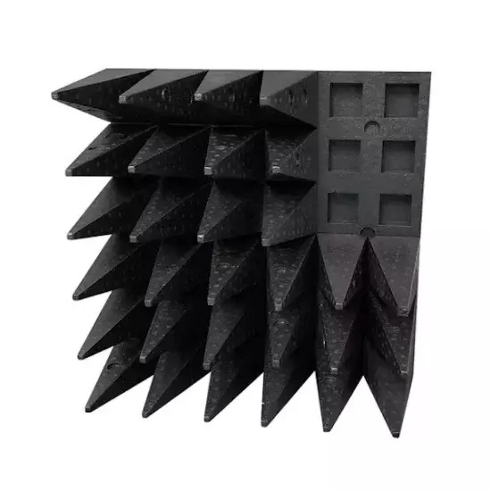
MVG's HyPyr-Loss™ Ultra UH Series uses carbon-loaded polypropylene pyramids designed to work with ferrite tiles. The series is intended for EMC chambers, including facilities used for pre-compliance and compliance testing.
The UH30, UH50, and UH75 models have different absorption characteristics. MVG publishes normal-incidence absorption figures for each model, allowing performance to be compared at specific frequencies.
Reference: MVG, UH Series datasheet . The published performance data applies to configurations using the specified ferrite tiles.
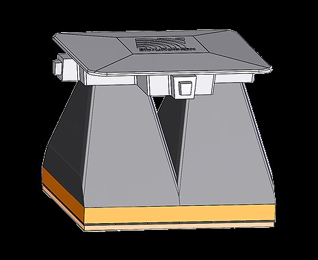
ETS-Lindgren's DuraSorb™ DSH-400H combines a rigid, uniformly loaded, closed-cell polystyrene absorber with a ferrite substrate. It is designed for EMC test chambers, including those used for MIL-STD-461 and CISPR 25 testing.
The absorber has a total height of 45.6 cm, including the ferrite tile base. Its closed-cell material is non-hygroscopic. The manufacturer also reports fire testing to UL 94 HBF and DIN 4102 B2.
Reference: ETS-Lindgren, DSH-400H datasheet v2.2
Not necessarily. Hybrid absorbers are designed to work with specific ferrite configurations. Before combining components, ask the manufacturer for performance data covering the exact pyramidal absorber and ferrite tile combination.
No. The published frequency range describes the absorber, while chamber performance also depends on the facility design and installation. The completed chamber must be validated against the required measurement conditions and test area.
Not always. Taller absorbers take up more chamber space, and their performance advantages depend on frequency. Compare the reflectivity data for individual models against the required test band and available space.
Reuse may be possible, depending on the condition and compatibility of the existing ferrite tiles. Ask the chamber supplier to assess the installation and include performance validation in the upgrade plan.
Next step
With your test requirements and chamber dimensions defined, compare suitable absorber configurations using the manufacturer guides above. Request model-specific performance data and confirm installation requirements before making a final selection.
The RF absorber market is expanding rapidly, driven by the increasing need for EMI (Electromagnetic Interference) reduction in 5G/6G, autonomous driving, and defense applications.
This site provides comparative information on products and manufacturers by application to help you identify the ideal solutions for R&D, anechoic chambers, and high-frequency testing.
Advertiser Disclosure:
We receive compensation from some of the companies listed below.This compensation may affect which companies are included and the order in which they appear.
| Frequency Range |
|---|
| 3GHz-320GHz |
| Material |
| Urethane Foam |
| Key Features |
| Up to 50 dB of absorption |
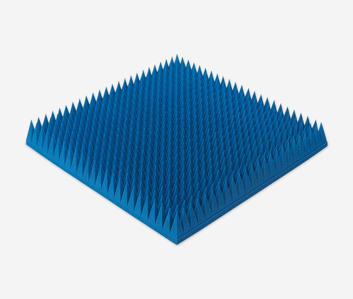
At just 550g per panel—approximately half the weight of competing products (*1)—this polyurethane foam absorber covers a wide frequency range from 3 to 320 GHz.
Delivers 50 dB absorption, outperforming conventional heavy ferrites.
Velcro-backed for rapid mounting, ideal for temporary setups and cost-effective maintenance.
| Frequency Range |
|---|
| 20MHz-3GHz |
| Material |
| Elastomer |
| Key Features |
| Permeability (at 1 MHz): 150 |
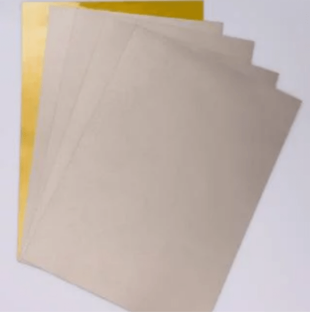
Heat-resistant elastomer: Designed for direct SMT processing and high-temperature durability.
Ultra-thin (from 0.1 mm) for high-density integration with robust EMI suppression.
It significantly reduces assembly workload and enables EMI countermeasures without altering the existing manufacturing process.
| Frequency Range |
|---|
| 1-35 GHz |
| Material |
| Elastomer |
| Key Features |
| Reflection Performance: –20 dB |
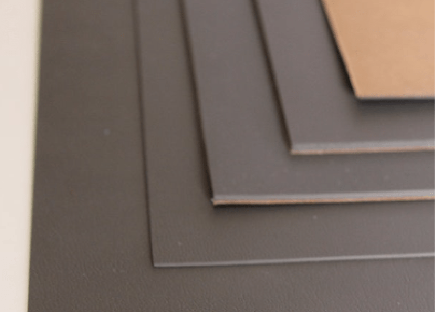
Frequency-tuned for specific radar absorption, offering superior stealth performance over standard RF sheets (*2).
Millimeter-thin design delivers –20 dB reflection, ensuring high absorption while preserving aerodynamic integrity.
Excellent conformance to complex geometries with thermal stability from –60°C to 150°C—ideal for aerospace platforms.