
RF absorber selection guide
Choose RF foam absorber by frequency, geometry, available depth, incidence angle, power exposure, environment, and mounting method. These conditions determine whether the material will control the unwanted energy in the installed setup.
Use the 7-point selection checklist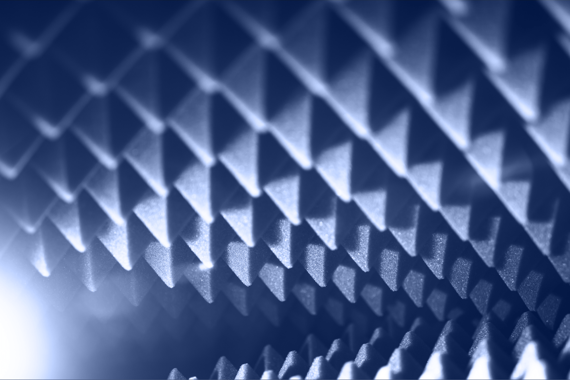
Start with the unwanted RF path. Chamber reflections, enclosure resonances, near-field scattering, and unwanted coupling call for different foam structures and placement strategies.
Use the exact grade data. A family-wide frequency range does not mean every thickness or pyramid height performs across that full range.
Protect the test geometry. Deeper absorber may improve low-frequency control but can reduce quiet-zone size, antenna distance, ventilation clearance, or access to the device under test.
Confirm installation conditions. Incidence angle, backing, power density, temperature, fire documentation, cleanliness, and mounting can change the practical result.
RF absorber foam is a lightweight electromagnetic absorber used to reduce reflected, scattered, or coupled radio-frequency and microwave energy. Common products use open-cell foam loaded or treated with electrically lossy material. Flat, multilayer, convoluted, and pyramidal structures shape how the electromagnetic field enters and travels through that material.
The purpose is measurement and field control. Reflections inside a shielded room, anechoic chamber, test box, cabinet, or fixture can create standing waves, disturb antenna patterns, change received power, and make repeated measurements difficult to compare.
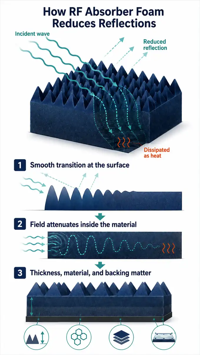
A taper, convolution, or dielectric gradient can reduce the abrupt mismatch between air and the lossy absorber. Less energy returns immediately from the front surface.
Energy that enters the absorber is dissipated as a small amount of heat while the field travels through the conductive or dielectric loss system.
Thickness, carbon loading, layers, seams, mounting surface, and any conductive or ferrite backing influence the installed performance.
Sources: Laird Performance Materials, Microwave Absorbing Foams; Hexcel, Dielectric Absorber Foam
The same “RF foam absorber” label can describe materials built for very different jobs. Identify where the unwanted energy travels and which surface is causing the error before comparing products.
| Observed problem | Likely starting point | What to verify |
|---|---|---|
| Broadband chamber reflections | Pyramidal foam or a chamber-specific hybrid system | Lowest frequency, required reflectivity, quiet-zone size, chamber validation, and available depth |
| Results change with small antenna, cable, or fixture movements | Convoluted foam or localized absorber around nearby scattering surfaces | Off-normal response, placement, polarization, coverage, and repeatability after each change |
| Resonance inside a compact enclosure or test box | Flat, lossy, reticulated, or multilayer foam | Available thickness, backing, target band, ventilation, and clearance around the device |
| Low-frequency EMC performance in limited chamber depth | Foam designed to work with ferrite tile | Impedance matching and performance of the complete foam-and-ferrite system |
| High field strength, continuous exposure, or elevated temperature | Purpose-built high-power or ventilated absorber | Continuous and pulsed limits, airflow, hot spots, test duration, and mounting temperature |
Sources: PPG, Anechoic Chambers; Hexcel, Dielectric Absorber Foam; Laird Performance Materials, Microwave Absorbing Foams
A useful shortlist describes the same band, geometry, backing, and exposure conditions as the real setup. Use these checks before comparing headline dB values.
Record the lowest and highest frequencies and the required reflection level at each critical point. The lowest frequency often drives the absorber depth.
Identify the wall, lid, floor, cable, fixture, corner, antenna edge, or nearby object producing the reflection or coupling path.
Include absorber depth in the chamber or enclosure layout. Protect antenna distance, quiet-zone size, device clearance, airflow, moving parts, and maintenance access.
Match frequency, incidence angle, polarization, test method, backing, sample size, and whether the published value is typical, minimum, or guaranteed.
Confirm continuous and pulsed exposure, duration, ventilation, ambient temperature, hot spots, and safe separation from heat-producing equipment.
Request the current fire-retardancy, cleanliness, environmental, and material-compliance documents for the exact grade. Standards such as NRL 8093 and UL 94 describe different test frameworks.
Confirm adhesive, hook-and-loop, mechanical retention, seams, cutting, removable panels, cleaning, spare pieces, and the RF effect of coatings or hardware.
| Published item | Why it matters | What to confirm |
|---|---|---|
| Frequency range | Performance varies across the band and by grade. | The usable range for the exact thickness, height, or part number |
| Reflectivity or reflection loss | Indicates the reflected signal under stated conditions. | Sign convention, test frequency, incidence, backing, and typical versus guaranteed status |
| Thickness or height | Strongly affects low-frequency behavior and occupied volume. | Total profile, base thickness, panel size, weight, and dimensional tolerance |
| Power handling | RF loss produces heat and may limit exposure. | Frequency, continuous or pulsed rating, airflow, ambient temperature, and duration |
| Environmental and fire data | Facility acceptance may depend on the exact test document. | Product grade, report revision, temperature, particles, humidity, UV, cleaning, and coating |
| Mounting and backing | Installation can alter the electromagnetic boundary condition. | Required metal or ferrite backing, adhesive thickness, orientation, seams, and hardware |
Product examples
These products illustrate three common directions: a compact millimeter-wave pyramid, a height-scaled ultra-wideband pyramid series, and a convoluted foam for wide incidence angles. Published values are model- and condition-dependent.
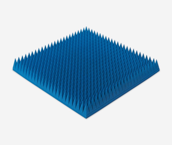
EC-SORB® ECP-3 is an 8.3 cm-high pyramidal urethane-foam absorber designed to maintain strong performance into the millimeter-wave band. Microwave Factory lists a current product frequency range of 3 to 100 GHz and publishes typical normal-incidence attenuation rising from 25 dB at 3 GHz to 50 dB from 24 through 100 GHz.
The 61 × 61 cm panel uses conductive carbon in a lightweight, flexible foam structure. The manufacturer also states that the absorber retains performance at large incidence angles, limits forward and backward scattering, supports optional hook-and-loop attachment, and meets UL 94 HBF requirements.
The manufacturer states that attenuation figures are representative, not guaranteed, and may change without notice.
See the manufacturer profile and related RF absorbers.
Explore Microwave Factory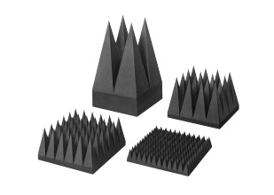
TDK IS is a pyramidal electromagnetic absorber series based on polyethylene foam and the ohmic loss of carbon. The published lineup ranges from 50 to 1,500 mm in length, allowing the selected grade to extend performance toward lower frequencies as absorber depth increases.
The datasheet lists typical vertical-incidence data from 0.1 to 110 GHz across the family. Coverage is grade-dependent: IS-005A begins its published table at 3 GHz, while IS-150 includes values from 0.1 GHz. The series is described as fire retardant to NRL Classes 1, 2, and 3 and UL 94 HBF. The same datasheet gives a representative power-withstand value of 50 mW/cm².
The TDK datasheet instructs users to request delivery specifications for current product details and safe use.
Review the manufacturer profile and related absorber products.
Explore TDK RF Solutions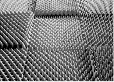
Eccosorb™ CV is a moderately flexible urethane-foam absorber with a rounded convoluted surface. Laird identifies it for millimeter-wave frequencies and very wide incidence angles, with no published degradation out to 60° off normal.
The current product page lists CV-3 and CV-4 with thicknesses of 67 and 98 mm, a product frequency range above 2 GHz, and reflectivity of −40 dB above 8 GHz. The page also lists a 90°C maximum operating temperature, UL 94 HBF, REACH, and RoHS compliance. The datasheet notes that coating can affect millimeter-wave reflectivity, so the supplied finish should be confirmed for the target band.
Published values are product-page or datasheet values; Laird advises testing the material in the intended application.
See the manufacturer profile and other foam absorber options.
Explore Laird TechnologiesNo. Acoustic foam controls sound reflections. RF absorber foam is formulated, structured, and tested for electromagnetic behavior. Appearance alone does not establish RF attenuation, power handling, or fire performance.
Greater depth generally helps extend useful performance toward lower frequencies, but thickness is not a universal predictor. Material loading, geometry, layers, backing, test method, and incidence angle also matter. Compare the curve or table for the exact grade.
Coverage follows the measurement objective. A fully anechoic chamber, semi-anechoic chamber, antenna shroud, compact test box, and device-level fixture require different treated surfaces. Model or measure the dominant reflection paths instead of assuming that maximum coverage is always the best layout.
Only when the foam is designed and validated for that ferrite system. The combined impedance relationship determines hybrid performance, so a general-purpose foam should not be treated as a drop-in substitute for a ferrite-matched grade.
Compare the same frequency, incidence angle, polarization, backing, sample geometry, and test method. Also check whether the number is reflectivity, reflection loss, return loss, absorption, or insertion loss and whether it is typical, minimum, or guaranteed.
Standard indoor foam may degrade under moisture, ultraviolet exposure, wind, temperature cycling, or mechanical wear. Use a purpose-built outdoor product or protected configuration and request RF data for that finished configuration.
Next step
Prepare the operating band, required reflectivity, chamber or enclosure dimensions, incidence geometry, power exposure, environment, and mounting constraints. This information makes product comparisons faster and reduces the risk of selecting a strong datasheet value that does not match the installation.
Compare 3 Recommended RF Absorbers by ApplicationAdvertiser Disclosure:
We receive compensation from some of the companies listed below.This compensation may affect which companies are included and the order in which they appear.
| Frequency Range |
|---|
| 3GHz-320GHz |
| Material |
| Urethane Foam |
| Key Features |
| Up to 50 dB of absorption |
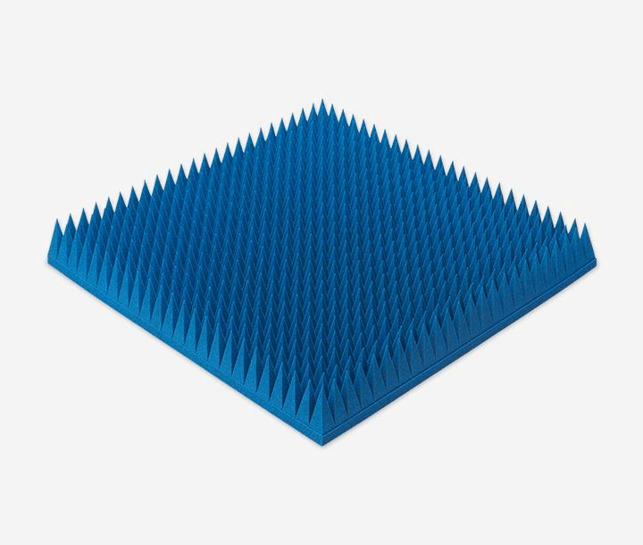
At just 550g per panel—approximately half the weight of competing products (*1)—this polyurethane foam absorber covers a wide frequency range from 3 to 320 GHz.
Delivers 50 dB absorption, outperforming conventional heavy ferrites.
Velcro-backed for rapid mounting, ideal for temporary setups and cost-effective maintenance.
| Frequency Range |
|---|
| 20MHz-3GHz |
| Material |
| Elastomer |
| Key Features |
| Permeability (at 1 MHz): 150 |
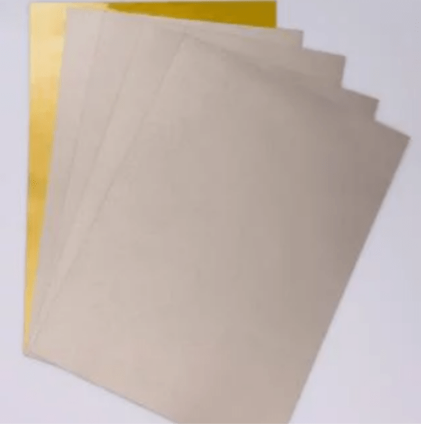
Heat-resistant elastomer: Designed for direct SMT processing and high-temperature durability.
Ultra-thin (from 0.1 mm) for high-density integration with robust EMI suppression.
It significantly reduces assembly workload and enables EMI countermeasures without altering the existing manufacturing process.
| Frequency Range |
|---|
| 1-35 GHz |
| Material |
| Elastomer |
| Key Features |
| Reflection Performance: –20 dB |
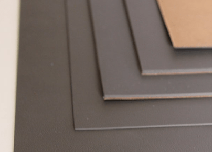
Frequency-tuned for specific radar absorption, offering superior stealth performance over standard RF sheets (*2).
Millimeter-thin design delivers –20 dB reflection, ensuring high absorption while preserving aerodynamic integrity.
Excellent conformance to complex geometries with thermal stability from –60°C to 150°C—ideal for aerospace platforms.