
Selection guide
A credible ECCOSORB alternative must match the application, loss mechanism, operating frequency, thickness, installation, and environmental requirements.
Start with the current ECCOSORB grade
A search for an ECCOSORB alternative often starts with price, lead time, or the need for a second source. Those concerns matter, but the installed material’s job comes first. An absorber used to damp a cavity resonance cannot be replaced on the strength of a similar-looking datasheet or a broad frequency claim.
The ECCOSORB range covers near-field noise suppression, cavity damping, surface-current control, free-space reflection reduction, isolation, and transmission-line applications. Alternative product lines are available from several manufacturers, but no single product replaces the whole range.
Record the current part number, thickness, location, backing, operating environment, and RF problem before building a shortlist.
ECCOSORB is a portfolio, not one material. Laird’s published selection information divides its absorbers by function, form, and frequency.
| ECCOSORB product family | Published role or frequency region | Information needed for comparison |
|---|---|---|
| RF-LB | Near-field noise suppression from 10 MHz to 4 GHz | Permeability, thickness, temperature limit, and distance from the noise source |
| MCS and RF-LW | Cavity-resonance control around 800 MHz to 6 GHz | Magnetic loss, attenuation at the problem frequency, thickness, and flame rating |
| BSR | Flexible absorber sheet for approximately 6 to 18 GHz | Material construction, loss data, flexibility, and installed thickness |
| GDS | Thin, high-loss absorber for approximately 18 to 35 GHz | Magnetic loading, attenuation data, thickness, and environmental limits |
| MMI, JCS-Next, and other high-frequency grades | Millimeter-wave applications above approximately 35 GHz | Dielectric or magnetic properties, geometry, and frequency-specific data |
| LS, AN, FGM, and other foam or free-space products | Isolation and reflection reduction | Foam structure, reflectivity, incidence angle, thickness, and mounting |
| MF, CR, CRS, and related stock or compound products | Loads, terminations, cast parts, and cavity damping | Form, machinability or cure process, complex material properties, and temperature |
A search based only on the ECCOSORB name mixes several unrelated requirements. The existing part may be a thin magnetic sheet, a tuned reflector, a lossy foam, or a machinable material inside a waveguide.
Reference: Laird RF Microwave Absorber Selection Guide [PDF]
The manufacturers below publish RF absorber families for applications that overlap parts of the ECCOSORB range. Their product lines provide a place to start, but each grade still has to be checked against the existing design.
| Manufacturer | Relevant product families | Published scope | Details to check |
|---|---|---|---|
| 3G Shielding | Wavexorb Narrowband, Cavity Resonance, Surface Wave, Low Frequency, and Dielectric Foam | Tuned absorption, cavity damping, surface-wave control, lower-frequency absorption, and broadband foam | Loss mechanism, peak frequency, thickness, test method, adhesive, and environmental limits |
| 3PB Solutions | US, LS, CB, XB, KU, KB, and KA Series | Acrylic and silicone absorber families divided by frequency band, including an 8 to 12 GHz XB Series | Performance curve, base material, thickness, temperature range, compliance, and fabrication |
| MAST Technologies | MR1, MR2, and MR3 | Tuned-frequency, cavity-resonance, and surface-wave absorbers | Grade-specific attenuation, thickness, substrate, cutting options, and installation conditions |
| PPG Cuming Microwave | C-RAM FLX, GDSS, FDSS, GDX, FFS, and other C-RAM families | Resonant, broadband, surface-wave, foam, castable, and machinable materials | Binder and filler system, frequency response, form, attachment method, and environmental limits |
A supplier page narrows the field. Qualification determines whether a particular grade can replace the material already used in the product.
Microwave Factory is a special case. Its current EC-SORB portfolio includes products that previously carried ECCOSORB model names.
In October 2025, Microwave Factory announced that affected products shipped from January 1, 2026, would use EC-SORB® in place of ECCOSORB®. The company stated that the specifications would remain unchanged. Examples included ECCOSORB® AN becoming EC-SORB® AN, ECCOSORB® LS becoming EC-SORB® LS, and ECCOSORB® MF becoming EC-SORB® MF.
| EC-SORB family | Published form or application |
|---|---|
| MF | Magnetically loaded machinable epoxy stock for absorbers, attenuators, waveguide loads, and terminations |
| SF | Thin resonant sheet absorber, with standard grades for selected frequencies from 1 to 16 GHz |
| GDS | Flexible, high-loss silicone rubber sheet |
| LS | Lightweight, flexible, high-loss foam sold in several thicknesses |
| FGM | Thin broadband sheet, including a published 5 to 8 GHz grade |
| MWP | Broadband millimeter-wave absorber for frequencies above 20 GHz |
The name change documents continuity within Microwave Factory’s product range. It does not document interchangeability with every product currently sold by Laird under the ECCOSORB name.
For a legacy part, compare the latest datasheets from both sources and note the manufacturer, model number, revision date, material, and test method. Microwave Factory should also confirm the current model corresponding to the old part number.
References: Microwave Factory EC-SORB Product List; Notification of Product Model Number Change
Define the job before comparing product names. Common requirements include near-field suppression, cavity damping, surface-wave attenuation, antenna isolation, reflection reduction, and termination of a transmission path.
A magnetically loaded elastomer used to lower cavity Q differs from carbon-loaded foam placed in a free-space path. Machinable epoxy in a waveguide termination is another category entirely. Shortlist products made for the same function as the current material.
A published operating range only shows where a supplier expects the material to be used. It does not state the loss at every frequency in that range.
Review the complete attenuation, reflectivity, insertion-loss, permeability, or permittivity data. For a narrowband problem, the absorption peak must fall at the required frequency with the proposed thickness and mounting arrangement.
A thicker grade can improve absorption at lower frequencies, but the part still has to fit. Check clearance, compression, bend radius, sheet size, weight, and any required air gap or conductive backing.
Available forms include solid sheet, foam, coating, castable compound, dispensable material, and machinable stock. Moving from one form to another changes the mounting method and often changes how the material interacts with the field.
Depending on the project, the material may need documented temperature performance, flammability, low outgassing, moisture resistance, chemical resistance, or freedom from silicone.
RoHS, REACH, UL, and similar declarations are grade-specific. They may also depend on the thickness, adhesive, or custom construction. Use documents for the exact configuration being purchased.
Check sheet sizes, pressure-sensitive adhesive, die-cutting, waterjet cutting, machining, molding, and other processing requirements.
Ask for current information on samples, minimum quantities, production lead times, lot traceability, and test reports. Catalogs and old distributor listings are unreliable sources for these commercial details.
Manufacturers do not always define frequency ranges in the same way. One range may show where measurable loss occurs. Another may mark the band in which a specified reflectivity target is reached.
| Published item | What it describes | What to verify |
|---|---|---|
| Reflection loss | Energy reflected under the stated measurement conditions | Frequency, backing, incidence angle, polarization, and sample geometry |
| Insertion loss | Change in transmitted or coupled energy after the material is added | Fixture, placement, reference condition, and measurement path |
| Attenuation per unit length | Loss through a stated thickness or propagation distance | Material properties, frequency, thickness, and interface effects |
| Permeability and permittivity | Complex material properties used for modeling RF behavior | Frequency-dependent real and imaginary values and measurement method |
| Published frequency range | The manufacturer’s stated application or measurement range | Whether every grade covers the full range and what performance threshold applies |
Compare curves measured under reasonably similar conditions. If matching data is unavailable, use the datasheet to select samples and test them. Do not use it as proof of equivalence.
Once the published specifications look plausible, move to controlled testing.
Record the full part number, thickness, backing, installed location, and purpose.
Identify the failing frequency or required result and document how it will be measured.
Choose materials with the same basic function, a suitable physical form, and published data at the required frequency.
Obtain samples in the thickness, adhesive, backing, and construction planned for production.
Evaluate each candidate in the enclosure, antenna, cavity, or transmission structure where it will be installed.
Confirm fit, adhesion, temperature behavior, durability, and required compliance documentation.
Test a production-representative lot before completing engineering and supply-chain approval.
Keep the existing material as the control. Otherwise, a change in placement, assembly, or measurement can look like a change in absorber performance.
Material price is only one part of the cost. Repeated EMC testing, new tooling, assembly changes, or another qualification cycle can erase the initial saving.
There is no universal replacement for the whole ECCOSORB portfolio. Suppliers may publish a cross-reference for a particular grade, but that recommendation still requires a review of frequency performance, thickness, material properties, mounting, and environmental documentation. Test the proposed replacement in the application.
For an 8 to 12 GHz design, study the performance curve within the frequencies the system actually uses. Then check thickness, backing, available space, temperature, and incidence conditions. Cavity resonance, surface currents, antenna isolation, and free-space reflections do not call for the same absorber. Products such as 3PB’s XB Series and frequency-appropriate grades from other suppliers provide starting points for testing.
Sometimes, but only when the foam meets the electrical, mechanical, and environmental requirements in its installed position. Foam and silicone sheets often use different loss mechanisms and occupy different amounts of space. They should not be treated as form-for-form substitutes.
Microwave Factory states that affected products were renamed from ECCOSORB® to EC-SORB® without a specification change. That announcement does not establish that every EC-SORB grade is interchangeable with every current Laird ECCOSORB product. Compare current datasheets and ask the manufacturers to confirm the relevant model numbers.
Technical fit comes first. Once candidates pass that screen, compare the installed and qualified cost. Include cutting, adhesive, assembly, testing, documentation, order quantity, lead time, and the risk of repeating part of the design cycle.
Next step
Search by application, frequency, form, and installation limits before choosing a manufacturer. Absorber Hub brings those factors together and links to official manufacturer information for further review.
Confirm the exact grade and current specification with the manufacturer before changing an existing design or bill of materials.
Explore Recommended RF Absorbers by ApplicationTrademark notice: ECCOSORB, EC-SORB, Wavexorb, C-RAM, and other product names are trademarks of their respective owners. Absorber Hub is an independent informational website and is not affiliated with or endorsed by the manufacturers referenced on this page.
Advertiser Disclosure:
We receive compensation from some of the companies listed below.This compensation may affect which companies are included and the order in which they appear.
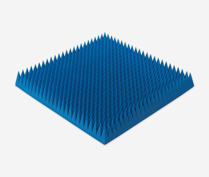
| Frequency Range |
|---|
| 3GHz-320GHz |
| Material |
| Urethane Foam |
| Key Features |
| Up to 50 dB of absorption |
At just 550g per panel—approximately half the weight of competing products (*1)—this polyurethane foam absorber covers a wide frequency range from 3 to 320 GHz.
Delivers 50 dB absorption, outperforming conventional heavy ferrites.
Velcro-backed for rapid mounting, ideal for temporary setups and cost-effective maintenance.
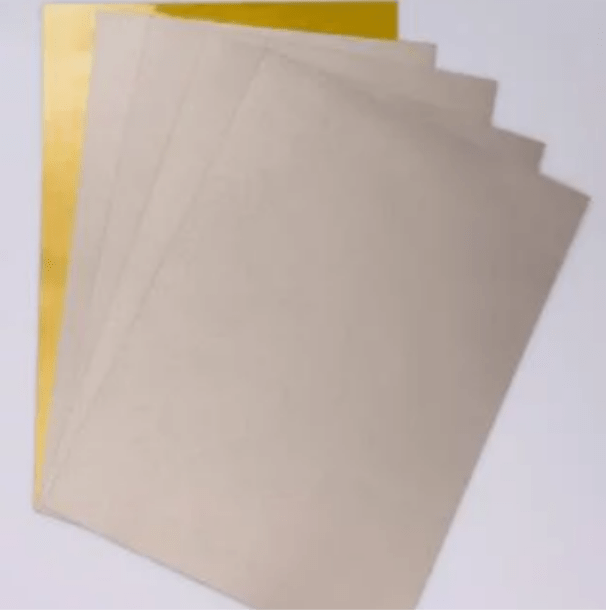
| Frequency Range |
|---|
| 20MHz-3GHz |
| Material |
| Elastomer |
| Key Features |
| Permeability (at 1 MHz): 150 |
Heat-resistant elastomer: Designed for direct SMT processing and high-temperature durability.
Ultra-thin (from 0.1 mm) for high-density integration with robust EMI suppression.
It significantly reduces assembly workload and enables EMI countermeasures without altering the existing manufacturing process.
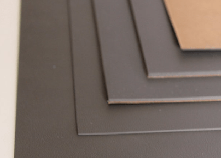
| Frequency Range |
|---|
| 1-35 GHz |
| Material |
| Elastomer |
| Key Features |
| Reflection Performance: –20 dB |
Frequency-tuned for specific radar absorption, offering superior stealth performance over standard RF sheets (*2).
Millimeter-thin design delivers –20 dB reflection, ensuring high absorption while preserving aerodynamic integrity.
Excellent conformance to complex geometries with thermal stability from –60°C to 150°C—ideal for aerospace platforms.