
RF absorber selection guide
RF absorbers are not interchangeable. The right choice depends on the electromagnetic problem, frequency range, available space, performance requirements, installation conditions, and test method.
Compare the main types of RF absorbers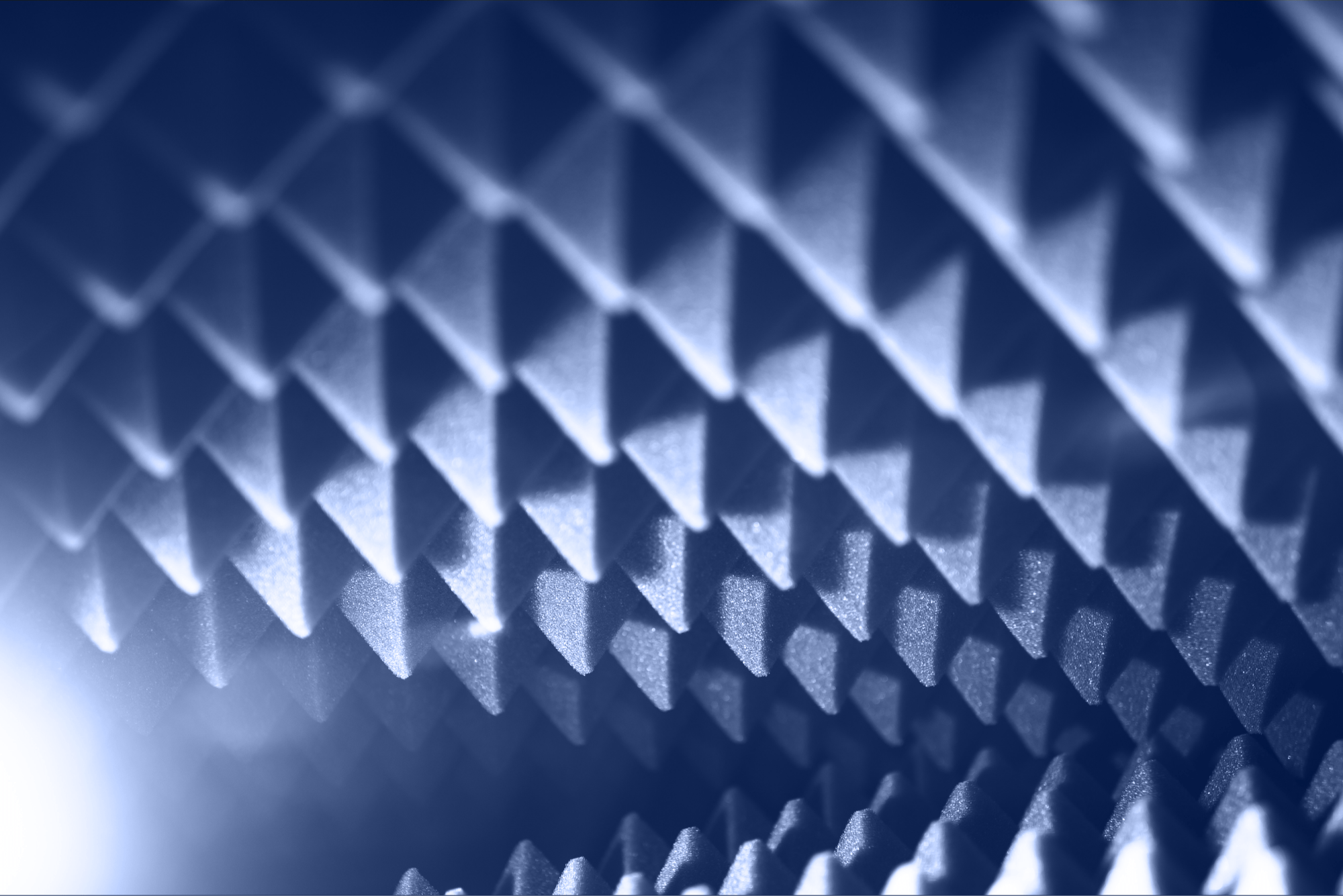
RF absorbers are used in everything from compact electronic assemblies to full-size anechoic chambers. They all reduce unwanted electromagnetic energy, but they are designed for different field conditions and installation environments.
A thin magnetic sheet placed near a PCB addresses a different problem than a pyramidal foam absorber installed in an antenna measurement chamber. Even when two products have the same published frequency range, differences in loss mechanism, thickness, geometry, backing, test method, power handling, and placement can produce very different results.
Start by identifying the unwanted electromagnetic behavior. You may need an RF absorber to:
Each application has different requirements. A product designed to suppress near-field noise may not be suitable for a large free-space measurement chamber. Before comparing products, identify where the absorber will be installed, which field or propagation path needs to be controlled, and how you will measure its performance.
Effective absorption begins with impedance matching. Energy reflected from the front surface cannot enter the material and be dissipated. Tapers, graded structures, multilayer products, and tuned sheets control the transition between free space and the lossy material.
Dielectric absorbers interact primarily with the electric-field component. Materials such as conductive carbon and silicon carbide may be dispersed in foam, rubber, resin, or another substrate. Magnetic absorbers use materials such as ferrites or carbonyl iron to interact with the magnetic-field component.
The absorber must attenuate the energy before it returns to the surrounding space. Thickness, surface profile, backing, placement, angle of incidence, and nearby structures all affect performance.
Material categories are useful, but your application should determine how you compare products. Document the following requirements before reviewing product families:
For electronic devices, absorber selection often depends on thickness, flexibility, adhesive compatibility, electrical insulation, and proximity to the noise source. For chamber projects, priorities include broadband reflectivity, geometry, low-frequency performance, fire safety, installation consistency, and usable test volume.
The categories below offer a starting point. Actual performance depends on the specific grade, thickness, geometry, backing material, and test conditions.
| RF absorber type | Typical uses | Main advantage | Key selection criteria |
|---|---|---|---|
| Magnetic or dielectric absorber sheet | PCBs, ICs, cables, antennas, housings, and compact assemblies | Thin and easy to install in tight spaces | Target frequency, thickness, permeability, flexibility, and adhesive system |
| Tuned or resonant absorber | Radar frequencies, narrowband reflection control, and selected surfaces | High attenuation near the design frequency | Center frequency, bandwidth, angle of incidence, and mounting surface |
| Lossy or reticulated foam | Cavities, free-space reflection control, and laboratory use | Lightweight and available in flat or shaped forms | Density, thickness, carbon loading, power handling, and durability |
| Pyramidal or wedge absorber | Anechoic chambers, antenna testing, radar measurements, and EMC facilities | Broadband free-space performance | Height, low-frequency limit, reflectivity, chamber volume, and fire performance |
| Ferrite tile | EMC chambers and low-frequency reflection control | Useful low-frequency performance at a shallow depth | Frequency response, mounting integrity, composition, and brittleness |
| Hybrid ferrite and foam | Broadband EMC and multipurpose chambers | Combines the lower-frequency performance of ferrite with the higher-frequency performance of foam | Material transition, total depth, chamber validation, and maintenance |
| Rigid, castable, machinable, or dispensable absorber | Loads, terminations, cavities, complex parts, and structural components | Can be formed or machined to fit application-specific geometries | Curing process, adhesion, thermal expansion, strength, and outgassing |
| Thermally conductive absorber | High-density or heat-generating electronic assemblies | Combines EMI control with heat transfer | Thermal conductivity, electrical isolation, compression, and RF attenuation |
Sheet absorbers are commonly used around components, circuit boards, cables, housings, and antennas. The published frequency range alone is not enough to choose a product. Thickness, magnetic properties, flexibility, adhesive, electrical insulation, temperature rating, and placement relative to the source can all affect performance.
A tuned absorber is designed for a specific frequency or relatively narrow band. It can substantially reduce reflections without the depth required by some broadband structures. The trade-off is less flexibility outside the design range.
Lossy foam is generally lightweight and can be cut or shaped for use in laboratories, enclosures, cavities, and free-space applications. When comparing products, review the exact geometry, thickness, reflectivity data, measurement frequencies, power rating, and flame-retardancy documentation.
A tapered profile creates a gradual transition from free space into the lossy material. Lower-frequency performance generally requires greater depth. Taller absorbers may improve performance, but they also reduce the space available for the quiet zone or working area.
Ferrite tiles are commonly used in lower-frequency EMC applications. A hybrid system adds foam or another tapered layer to extend performance into higher frequency ranges. The ferrite, foam, mounting method, seams, doors, floor treatment, and chamber layout all affect the completed site's performance.
You may need an alternative because of cost, availability, lead times, regional sourcing needs, discontinued grades, environmental requirements, or a need for better technical support.
Use the current product as your baseline. Record its exact grade, thickness, dimensions, backing, installation method, performance across the frequency range, environmental limits, and role in the system. Comparing only brand names or nominal frequency ranges carries a high risk of choosing an unsuitable replacement.
ECCOSORB is a broad product family, not a single material specification. Potential alternatives may include relevant product lines from 3G Shielding Specialties, 3PB Solutions, MAST Technologies, PPG Cuming Microwave, and other specialist suppliers. Microwave Factory needs to be considered separately: certain former ECCOSORB model names transitioned to EC-SORB branding, so these products are not unrelated substitutes.
The right candidate depends on the original grade and its function. Foam chamber absorbers, tuned elastomers, cavity absorbers, load materials, and thin near-field sheets each require different comparison criteria.
Sheets are generally thin and suited to localized control in electronic equipment, housings, antennas, and compact cavities. Foam comes in flat or shaped forms and is often used for cavity treatment, free-space reflection control, and anechoic environments.
Not necessarily. They may differ in thickness, geometry, loss mechanism, backing, test method, temperature rating, power handling, and response to the angle of incidence. Compare the full specifications and test the candidate in the intended application.
They can be, but price alone does not establish equivalence. Review comparable technical data, quality controls, environmental requirements, manufacturing consistency, and test results from the intended application.
Ferrite is commonly considered for lower-frequency EMC chamber applications where the depth required for foam may be impractical. Hybrid systems combine ferrite with foam or another lossy structure to extend performance across a broader frequency range.
Composition provides useful clues, but it does not determine final performance on its own. Thickness, geometry, impedance matching, backing, placement, and surrounding structures also affect the result.
Advertiser Disclosure:
We receive compensation from some of the companies listed below.This compensation may affect which companies are included and the order in which they appear.
| Frequency Range |
|---|
| 3GHz-320GHz |
| Material |
| Urethane Foam |
| Key Features |
| Up to 50 dB of absorption |
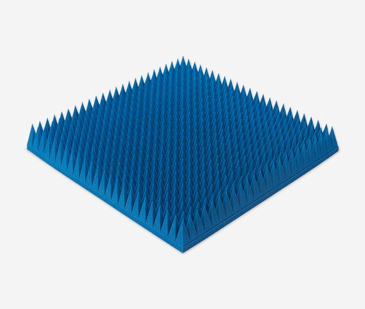
At just 550g per panel—approximately half the weight of competing products (*1)—this polyurethane foam absorber covers a wide frequency range from 3 to 320 GHz.
Delivers 50 dB absorption, outperforming conventional heavy ferrites.
Velcro-backed for rapid mounting, ideal for temporary setups and cost-effective maintenance.
| Frequency Range |
|---|
| 20MHz-3GHz |
| Material |
| Elastomer |
| Key Features |
| Permeability (at 1 MHz): 150 |
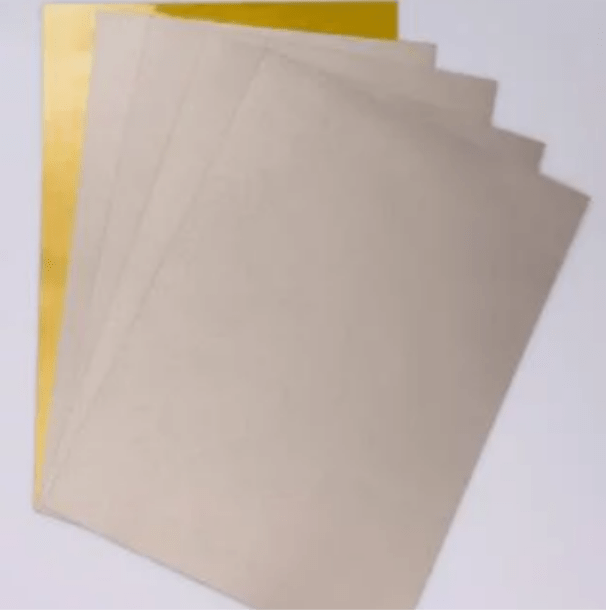
Heat-resistant elastomer: Designed for direct SMT processing and high-temperature durability.
Ultra-thin (from 0.1 mm) for high-density integration with robust EMI suppression.
It significantly reduces assembly workload and enables EMI countermeasures without altering the existing manufacturing process.
| Frequency Range |
|---|
| 1-35 GHz |
| Material |
| Elastomer |
| Key Features |
| Reflection Performance: –20 dB |
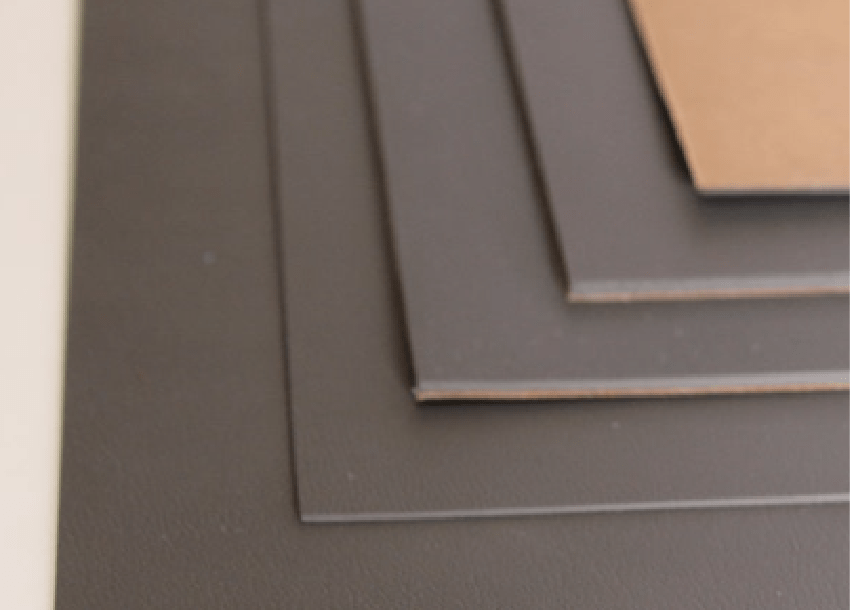
Frequency-tuned for specific radar absorption, offering superior stealth performance over standard RF sheets (*2).
Millimeter-thin design delivers –20 dB reflection, ensuring high absorption while preserving aerodynamic integrity.
Excellent conformance to complex geometries with thermal stability from –60°C to 150°C—ideal for aerospace platforms.