
Selection brief
The right absorber is determined by frequency, required reflectivity, incidence angle, power density, fire performance, installation method, and available chamber space.
Use the 7-point selection checklist
A pyramidal RF absorber is a radiation-absorbent material formed as an array of tapered pyramids, usually on a square panel. Many conventional chamber absorbers use low-density polyurethane foam impregnated with conductive carbon. Other substrates and geometries are available for high-power, cleanroom, outdoor, or mechanically demanding environments.
These absorbers are installed on reflective surfaces inside a shielded enclosure or around a measurement range. The shielded enclosure limits electromagnetic energy coupled from outside, while the absorber reduces reflections generated inside the test space.
Pyramidal absorbers are widely used because one structure can provide broadband behavior across a large frequency span. Actual coverage is model-dependent. A short panel may perform well at microwave and millimeter-wave frequencies, while operation at lower frequencies generally requires a taller absorber, a tuned design, or a hybrid construction that combines foam with ferrite tile.
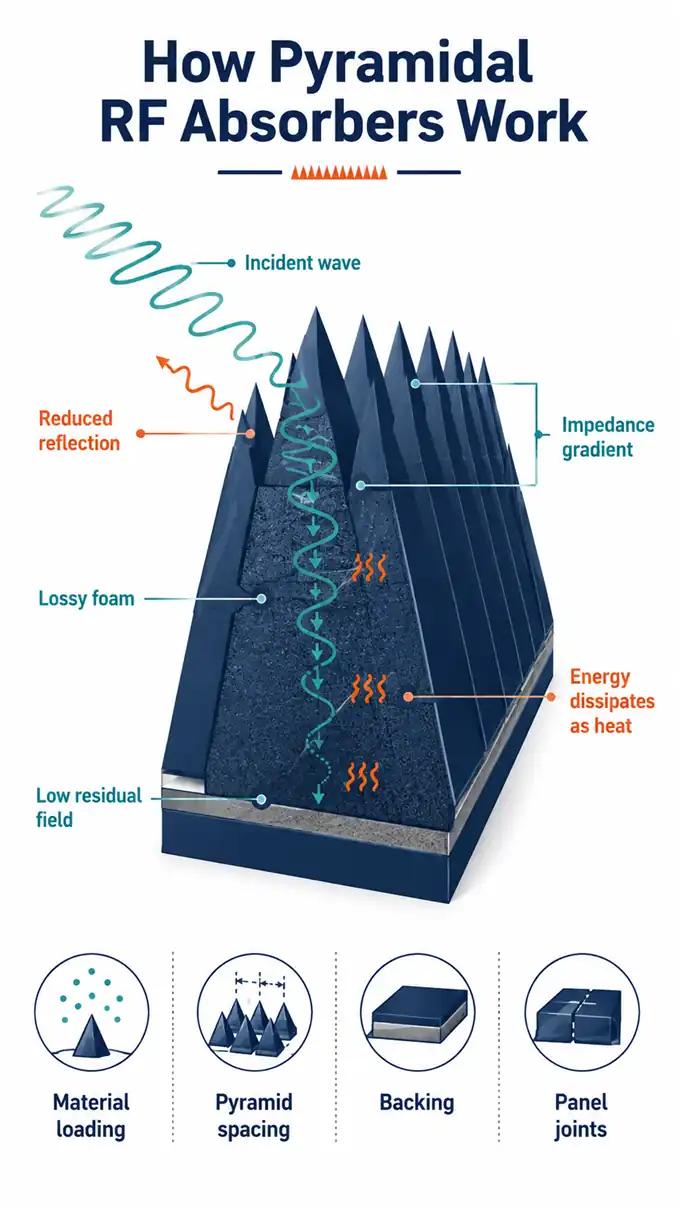
A flat interface between air and a materially different surface can produce a strong reflection. A pyramid introduces the absorber gradually: the wave first encounters the narrow tip and then an increasing volume of lossy material toward the base. This geometric taper creates an impedance gradient that reduces the abrupt mismatch at the front surface.
Part of the incident field enters the conductive, lossy foam instead of returning directly toward the source. As the field travels through the material, electromagnetic energy is dissipated as a small amount of heat. Depending on the incidence angle, a reflected component may encounter another pyramid surface, where partial transmission and attenuation occur again. By the time the remaining field reaches the base, its amplitude can be substantially reduced.
The visible pyramid is only one part of the design. Conductive loading, foam density, pyramid spacing, base thickness, panel joints, mounting surface, and any ferrite backing influence performance. Gaps, damaged tips, incorrect orientation, or poorly fitted corners can create reflection paths that are not apparent from a single-panel datasheet.
References: Microwave Factory EC-SORB® VHP; COMSOL Modeling of Pyramidal Absorbers for an Anechoic Chamber
Longer wavelengths are harder to attenuate within a shallow structure. For that reason, manufacturers typically offer the same absorber family in several heights. Published product tables from Microwave Factory, PPG, and MVG show the same broad pattern: taller grades extend useful reflectivity toward lower frequencies, while shorter grades are intended for higher-frequency operation.
Height should not be selected from a universal inches-to-frequency rule. Two absorbers of the same height can differ in material formulation, taper, base design, test method, and reported performance. Start with the lowest operating frequency and required reflectivity, then compare the manufacturer’s curve or table for the exact model.
Manufacturers commonly report performance as reflectivity, reflection loss, or return loss in decibels. Some tables show negative values such as −30 dB, while others list the attenuation magnitude as 30 dB. In either format, greater attenuation indicates a smaller reflected signal. The number is meaningful only when its measurement conditions are known.
| Published item | Why it matters | What to confirm |
|---|---|---|
| Frequency | Performance changes across the operating band. | Minimum and maximum test frequencies for the exact grade. |
| Reflectivity or reflection loss | Indicates how much of the incident field is reflected under stated conditions. | Whether the value is typical or guaranteed and whether the sign is shown. |
| Incidence angle | Normal-incidence performance may not represent sidewall, ceiling, or bistatic use. | Off-normal data at the angles relevant to the chamber layout. |
| Test method | Waveguide, coaxial, NRL arch, monostatic, and bistatic methods do not describe identical setups. | Sample size, polarization, backing material, distance, and calibration method. |
| Absorber height | Strongly affects low-frequency behavior and occupied chamber volume. | Total height, pyramid height, base thickness, panel size, and weight. |
Pyramidal absorbers are most valuable where uncontrolled reflections would distort a field or measurement. Common applications include:
Absorber selection must follow the facility’s measurement objective. A material suitable for a low-power antenna range may not be suitable for high-field immunity testing, outdoor exposure, a cleanroom, or a floor area exposed to foot traffic.
| Absorber type | Typical reason to use it | Main point to evaluate |
|---|---|---|
| Conventional pyramidal foam | Broadband treatment of chamber walls, ceilings, floors, and back walls. | Height versus low-frequency performance and available chamber volume. |
| Truncated or blunt-tip pyramid | Reduced profile or improved resistance to tip damage. | Possible high-frequency trade-off compared with a sharp pyramid. |
| Wedge or convoluted absorber | Special chamber areas, directional layouts, or spaces where a conventional pyramid is not preferred. | Orientation, polarization sensitivity, usable bandwidth, and placement. |
| Hybrid ferrite and foam | Low-frequency EMC performance where a foam-only design would consume too much chamber depth. | Impedance matching between the foam and ferrite tile across the full band. |
| High-power or ventilated absorber | High field strengths, air ducts, forced-air cooling, or elevated thermal load. | Substrate, airflow, continuous and pulsed limits, hot spots, and test duration. |
A specialized geometry should be selected from chamber-level requirements rather than treated as a drop-in equivalent. For example, a truncated absorber designed for installation over ferrite tile may save space, but its high-frequency behavior can differ from that of a full sharp pyramid. Likewise, a high-power honeycomb or reticulated-foam absorber addresses thermal demands that conventional polyurethane foam may not support.
References: Compliance Engineering, Pyramidal RF Absorber: SMT Version; PPG Anechoic Chamber Materials; ETS-Lindgren High Power Microwave Absorber
List the lowest and highest frequencies, then define the required reflectivity by frequency and chamber surface. Avoid selecting from a family-wide frequency range alone; the lowest published frequency may apply only to the tallest grade.
Back walls, sidewalls, ceilings, and floors do not receive energy at the same angles. Ask for normal and off-normal data when wide-angle performance affects the quiet zone or the intended measurement geometry.
Taller absorber may improve low-frequency performance but reduces the clear internal dimensions of the chamber. Include the absorber profile, turntable, antenna travel, test-object envelope, walkway, doors, lighting, cameras, penetrations, and ventilation paths in the layout review.
Power capability depends on frequency, exposure duration, airflow, ambient temperature, material, and installation. Compare continuous and pulsed ratings separately. High-power areas may require reticulated foam, honeycomb structures, forced air, thermal analysis, or additional spacing.
Confirm the exact product grade and current test documentation required for the facility. NRL 8093, UL 94, ASTM E84, DIN 4102-B2, and other references describe different test frameworks; a general “fire-retardant” statement is not a substitute for the specified report or certification.
Standard indoor foam may need a coating or a purpose-built alternative in humid, outdoor, dusty, cleanroom, vacuum, high-traffic, or mechanically exposed locations. Any protective treatment should be backed by RF-performance data for the relevant band.
Adhesive, hook-and-loop fasteners, and clip-and-rail systems support different replacement and load requirements. Confirm wall and ceiling limits, panel orientation, seams, corner pieces, access to utilities, cleaning methods, spare panels, and the effect of mounting hardware on the RF surface.
Reference: ETS-Lindgren, Top 10 Anechoic Absorber Considerations for RF and Microwave
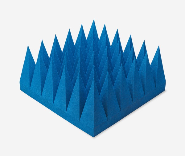
EC-SORB® VHP is a panel-type broadband absorber made from conductive-carbon-loaded polyurethane foam. Microwave Factory describes the series as suitable for normal and wide-angle incidence and for reducing forward and backward scattering in anechoic chambers.
The 24 × 24 in. (61 × 61 cm) panels are available in heights from approximately 4 to 45 in. (11 to 114 cm). The published performance table shows how the taller grades extend the useful range toward lower frequencies: VHP-45 lists typical attenuation from 200 MHz, while the shorter VHP-4 starts at 3 GHz in the table.
The lightweight, flexible foam can be installed with chloroprene adhesive or optional hook-and-loop fastening for easier removal. The manufacturer states that the product meets UL 94 HBF requirements and the cited NRL report tests. Published attenuation figures are typical values rather than guaranteed values, so the exact grade should be checked against the required frequency and chamber geometry.
Reference: Microwave Factory Official Website
Microwave Factory Co., Ltd.
Learn more about Microwave Factory’s RF absorbers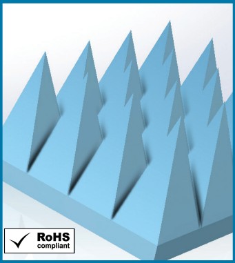
C-RAM SFC is a broadband pyramidal absorber made from specially treated, low-density polyurethane foam. Its steep pyramid design creates an impedance gradient, and PPG publishes both normal-incidence and bistatic off-normal performance information for chamber and radar-range design.
The series ranges from 3 to 96 in. in height on standard 24 × 24 in. panels. PPG’s table spans test frequencies from 0.08 to 50 GHz, but each grade covers a different portion of that range. Typical reflectivity reaches 60 dB for some grade-and-frequency combinations. The taller models are intended for lower-frequency performance, while shorter panels provide a smaller profile at higher frequencies.
Standard installation uses contact adhesive. Grades through 24 in. can also be supplied with hook-and-loop backing, and a clip-and-rail system is available. PPG states typical power handling up to 1.0 W/in² (1.55 kW/m²) in a temperature-controlled room, subject to frequency and application. The current technical data sheet also lists NRL 8093, ASTM E84 Class A, and UL 94 HF-1 among its fire-retardancy references.
Reference: PPG (Cuming Microwave) Official Website [PDF]
PPG (Cuming Microwave)
Learn more about PPG (Cuming Microwave)’s RF absorbers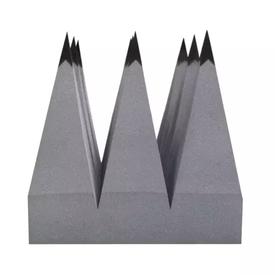
MVG’s AEP Series is a broadband pyramidal absorber family published for frequencies from 30 MHz to 40 GHz. The lineup covers heights from 4 to 96 in. on a standard 24 × 24 in. base, allowing the chamber designer to match absorber depth to the low-frequency requirement.
The series uses more than one geometry depending on model and performance requirements. MVG’s published data shows normal-incidence absorption generally improving with frequency and absorber height, with values reaching 50 dB for many model-and-frequency combinations. Hollow versions listed in the product sheet reduce weight and are designed to enhance lower-frequency performance.
The AEP sheet identifies the series for anechoic chambers, test boxes, fixtures, and ranges. It lists indoor use, NRL 8093, ISO 11925-2, and DIN 4102-B2 references, along with an optional rubberized coating intended to increase durability and service life. Confirm the current geometry designation and environmental option for the selected grade before specifying it.
Reference: Microwave Vision Group Official Website
Microwave Vision Group (MVG)
Learn more about Microwave Vision Group’s RF absorbersNo. Acoustic foam is designed to reduce sound reflections in air. RF absorber foam is formulated and tested for electromagnetic behavior, often through conductive loading and a controlled geometry. Similar appearance does not make the materials interchangeable.
Start with the lowest required frequency, reflection target, angle of incidence, and available chamber depth. Then use the exact manufacturer performance table or curve for that model. A family-wide frequency range does not mean every height performs across the entire range.
Only when the foam design is compatible with the ferrite system. Hybrid absorbers depend on the impedance relationship between the foam and tile, so a general-purpose pyramid should not be substituted for a ferrite-matched model without chamber-level validation.
Standard products are often specified for indoor use. Outdoor ranges require an absorber or protective treatment designed for moisture, ultraviolet exposure, wind, temperature cycling, and mechanical wear. Request RF data for the coated or protected configuration rather than assuming the untreated performance remains unchanged.
Compare the same frequency, incidence angle, polarization, backing condition, and test method. Also check whether values are typical, minimum, or guaranteed. When chamber accuracy is critical, evaluate installed-system validation and quiet-zone performance in addition to individual-panel data.
Check
The right RF absorber depends on the operating band, target reflectivity, chamber geometry, field strength, and installation environment. Compare product data by application and confirm the exact grade with the manufacturer before final chamber design.
This site provides comparative information on products and manufacturers by application to help you identify candidate solutions for R&D, anechoic chambers, and high-frequency testing.
Explore 3 Recommended RF Absorbers by ApplicationAdvertiser Disclosure:
We receive compensation from some of the companies listed below.This compensation may affect which companies are included and the order in which they appear.
| Frequency Range |
|---|
| 3GHz-320GHz |
| Material |
| Urethane Foam |
| Key Features |
| Up to 50 dB of absorption |
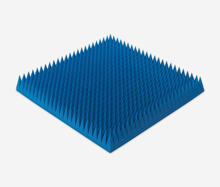
At just 550g per panel—approximately half the weight of competing products (*1)—this polyurethane foam absorber covers a wide frequency range from 3 to 320 GHz.
Delivers 50 dB absorption, outperforming conventional heavy ferrites.
Velcro-backed for rapid mounting, ideal for temporary setups and cost-effective maintenance.
| Frequency Range |
|---|
| 20MHz-3GHz |
| Material |
| Elastomer |
| Key Features |
| Permeability (at 1 MHz): 150 |
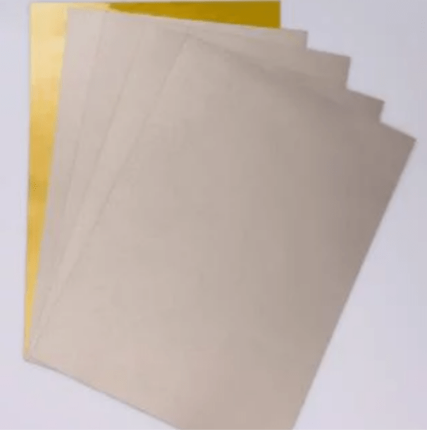
Heat-resistant elastomer: Designed for direct SMT processing and high-temperature durability.
Ultra-thin (from 0.1 mm) for high-density integration with robust EMI suppression.
It significantly reduces assembly workload and enables EMI countermeasures without altering the existing manufacturing process.
| Frequency Range |
|---|
| 1-35 GHz |
| Material |
| Elastomer |
| Key Features |
| Reflection Performance: –20 dB |
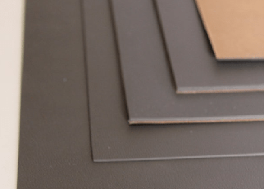
Frequency-tuned for specific radar absorption, offering superior stealth performance over standard RF sheets (*2).
Millimeter-thin design delivers –20 dB reflection, ensuring high absorption while preserving aerodynamic integrity.
Excellent conformance to complex geometries with thermal stability from –60°C to 150°C—ideal for aerospace platforms.